Why is material building up on one side of a horizontal vibrating screen?
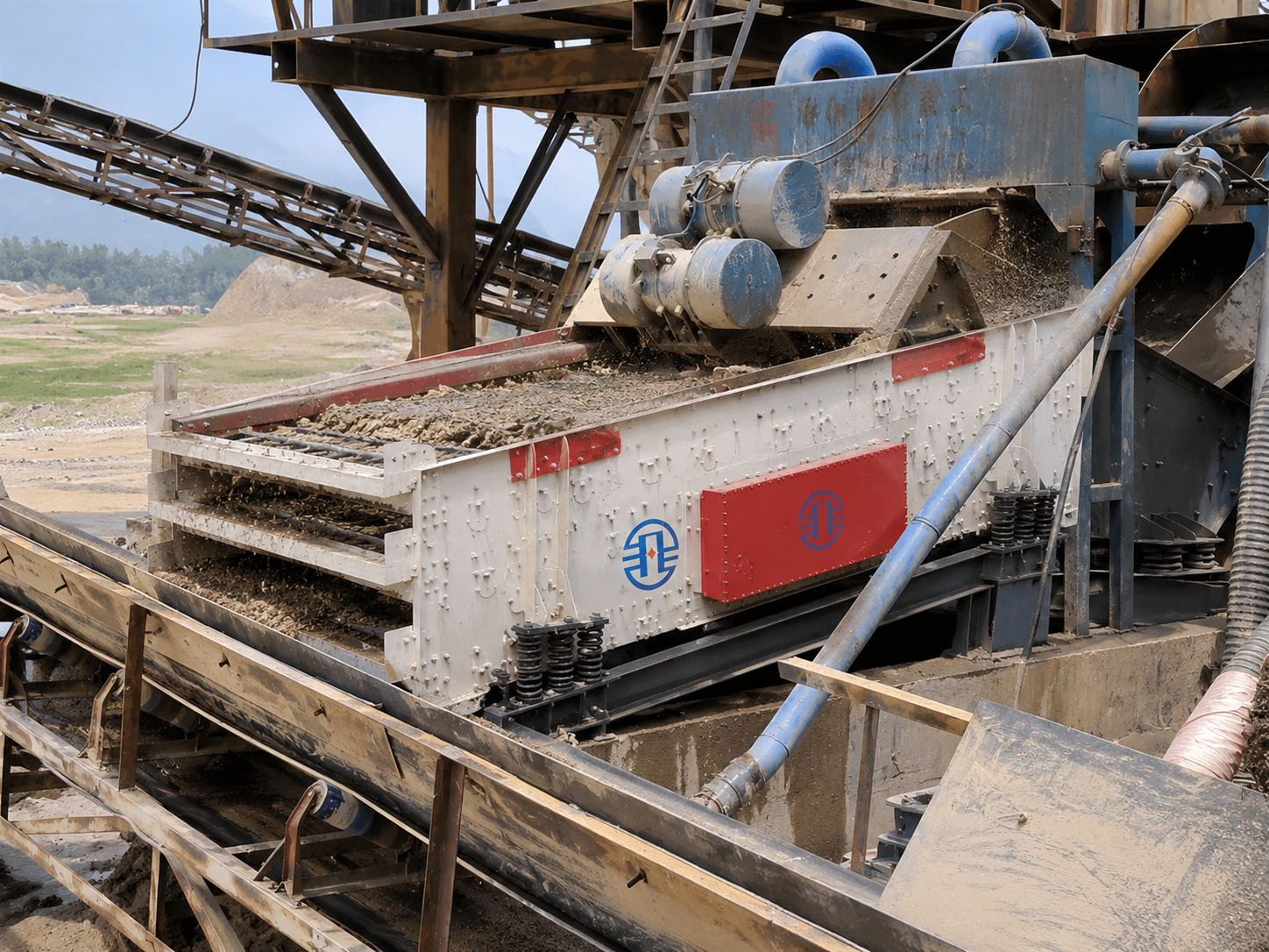
Material building up along one side of a Horizontal Vibrating Screen usually points to uneven feeding, a side-to-side support problem, unequal vibration, or restricted flow through part of the deck. Start by locating where the imbalance begins: material entering off-center suggests a feed problem, while an evenly fed bed that gradually moves sideways calls for closer examination of the machine’s support and motion.
Replacing the screen media before identifying that pattern often leaves the cause unresolved. First establish whether material is arriving unevenly, traveling unevenly, or passing through the deck unevenly. Each condition requires a different correction.
Locate the first point where the bed becomes uneven
Observe the feed end, middle, and discharge end from designated safe positions with guards in place. Compare bed depth and travel on both sides at a steady feed rate. A brief surge is less informative than a persistent pattern. Also distinguish sideways movement from material simply traveling more slowly along one edge.
Record whether the change followed screen replacement, spring work, exciter maintenance, a chute adjustment, or a change in material moisture. The timing helps narrow the investigation, although it does not establish the cause by itself.
Correct feed placement and sideways momentum
A centered chute does not guarantee centered loading. Material leaving an upstream belt retains momentum, and a transfer chute can direct that stream toward one sidewall. Observe where the stream lands and the direction in which it spreads. A narrow stream landing near the center can still push material sideways if it enters at an angle.
With the equipment isolated, inspect the chute for adhered fines, worn liners, displaced deflectors, and obstructions that reduce its effective width. Wet sand collecting on one wall can redirect the stream even when the chute’s external position has not changed. Worn impact surfaces can gradually alter the landing point.
Restore the intended feed path and distribution across the usable deck width. Any spreader or deflector must suit the material size and available chute clearance; an improvised plate that catches oversized stone can create a new blockage. Avoid using higher vibration intensity to compensate for a concentrated feed stream.
Compare operating conditions as well. If uneven loading appears when an upstream conveyor carries material along one edge, address that tracking or loading issue before repeatedly adjusting the screen inlet.
Verify support geometry before changing machine settings
A side-to-side height difference can encourage material to collect along the lower edge. However, spirit-level readings taken on random guards or panels are unreliable. Use the manufacturer’s reference points and specified installation geometry. The machine’s intended longitudinal arrangement must remain intact while transverse alignment is assessed.
Before entering guarded areas, clearing material, or taking physical measurements, stop and isolate the screen and connected equipment against unexpected starting. Account for stored energy and support requirements before working on springs or raised components. Never loosen a spring assembly under an unsupported screen body.
Compare the support seats, spring seating, and screen-body clearances. Look for broken coils, displaced springs, damaged rubber elements where fitted, settled foundations, loose base connections, and material packed around the supports. Contact with a chute, guard, or accumulated stone can restrict movement on one side and resemble a suspension fault.
Unequal spring compression alone does not prove a spring has failed. Off-center material loading also changes support loads. Compare measurements under the manufacturer’s specified condition, including an empty deck where required, and confirm that corresponding springs have the correct specification and installed arrangement.
Do not add shims simply to make the visible material bed look level. Correct the underlying support defect, then verify alignment and clearances against the installation requirements.
When the feed is even, compare vibration on both sides
If material enters uniformly but separates sideways farther down the deck, unequal motion becomes a stronger suspect. Relevant faults include loose exciter mountings, bearing damage, incorrect eccentric-weight settings, drive problems, or synchronization faults on machines designed with synchronized exciters.
Exciter layouts differ. Some screens use mechanically coupled shafts; others rely on a specified relationship between separate drives. Rotation direction, shaft timing, and weight settings must follow the machine documentation. Changing one eccentric weight to “push material back” can introduce twisting forces and increase structural stress.
Compare stroke and motion direction at corresponding locations on the screen body using approved measurement points and suitable vibration instruments. Take readings under the same operating condition. Measurements from different longitudinal positions are not directly interchangeable, and an overall vibration reading from one bearing cannot establish that the two sides move equally.
A marked left-to-right difference warrants investigation of the drive, fasteners, and screen structure. Inspect for cracked crossmembers, damaged side plates, or loose connections during shutdown. If there is visible structural damage, impact between components, or a sudden severe change in vibration, stop operation until the cause is assessed. Continued running can extend the damage.
Separate poor passage from poor conveying
A thick strip of material does not always indicate that particles have migrated sideways. If apertures on one side are blinded by damp fines or pegged with near-size particles, less material passes through there. The retained bed becomes deeper even when conveying motion remains reasonably balanced.
During isolation, compare equivalent areas across the deck. Examine aperture blockage, panel condition, tensioning or fastening, and the space beneath the media. On a multi-deck screen, a local accumulation on a lower deck can be difficult to identify from observations at the top deck alone.
Replacement media also deserves attention. Panels that fit the same opening can differ in aperture geometry, open area, thickness, and surface profile. Mixing unlike panels across the width can produce unequal passage or travel resistance. Restore the specified arrangement instead of assuming that identical nominal aperture sizes provide identical screening behavior.
A raised panel edge, loose clamp, damaged side liner, or trapped stone can slow material along one side. Correct these local restrictions before considering changes to speed or throw. For wet screening, compare spray coverage and blocked nozzles: uneven washing can leave one side more heavily blinded. Keep water adjustments within the process and equipment limits.
Confirm the correction under a stable load
After repairs, restore guards and follow the prescribed startup sequence. Establish normal operating motion before introducing a controlled feed, then observe the same locations used during the initial assessment. Change one operating variable at a time so its effect remains identifiable.
Judge the result by more than an apparently flatter bed. Compare material travel, discharge distribution, local accumulation, and product separation. Reducing throughput may conceal the symptom while leaving the original cause in place.
Record the feed condition, material moisture, installed media, and any measured support or vibration differences. If uneven loading returns only with a particular material or production rate, those observations provide a concrete starting point for the next investigation.
Leave A Message
If you are interested in our products and want to know more details, please leave a message here, we will reply you as soon as we can.